(1).png "PowerHome.com")
Choosing between a PWM and an MPPT solar charge controller is often presented as a simple decision: PWM for small systems and MPPT for larger ones. While that rule can be a useful starting point, it is not enough to design a safe, efficient solar charging system.
The most expensive mistakes usually happen when buyers focus only on solar panel wattage or the controller’s amp rating. A controller marked “100V / 30A,” for example, does not simply mean it can handle any 100V, 30A solar system. The 100V rating may refer to the maximum PV open-circuit voltage, while the 30A rating may refer to maximum battery-side charging current. Those are entirely different limits.
Before choosing PWM or MPPT, you need to understand the controller label, the electrical characteristics of your solar panels, how panels are wired together, and what your battery actually requires. This guide explains the specifications that matter most and helps you avoid common solar charge controller selection mistakes.
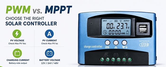
1. Do Not Choose by Watts Alone: Read the Controller Label First
Solar panel wattage is important, but it should never be the only number used to select a solar charge controller.
A solar controller normally has at least three separate electrical limits:
-
Maximum PV open-circuit voltage
-
Maximum PV short-circuit current
-
Maximum battery charging current
These values describe different parts of the system.
Maximum PV Open-Circuit Voltage: Check Voc Before Connecting Panels
Voc means open-circuit voltage. It is the voltage a solar panel produces when it is not connected to a load.
When solar panels are wired in series, their voltages add together.
For example, if one panel has a Voc of 45V:
-
Two panels in series = 90V Voc
-
Three panels in series = 135V Voc
If your MPPT controller has a maximum PV open-circuit voltage rating of 100V, a three-panel series string would be unsafe. Even two panels may be too close to the limit once cold-weather voltage rise is considered.
Solar panels produce higher voltage in cold conditions. This is why the array Voc should be calculated using the lowest expected local temperature, not just the standard test condition listed on the panel label.
A simplified way to think about it is:
Cold-weather array Voc = panel Voc after temperature correction × number of panels in series
Always leave a safety margin. Do not design a PV string so that its calculated cold-weather Voc is equal to the controller’s absolute maximum voltage.
A 100V controller should not be treated as a system that can safely operate at exactly 100V in every season and weather condition. In cold, bright conditions, a PV array may exceed its normal rated Voc.
Maximum PV Short-Circuit Current: Check Isc for Parallel Strings
Isc means short-circuit current. It is the maximum current a panel can produce when its positive and negative terminals are directly connected.
When solar panels are wired in parallel, their currents add together.
For example, if one panel has an Isc of 13A:
-
Two panels in parallel = 26A Isc
-
Three panels in parallel = 39A Isc
-
Four panels in parallel = 52A Isc
The controller must be rated to safely accept the total PV short-circuit current of the array.
Do not confuse Isc with the controller’s battery charging current. A controller may have a 30A battery charging rating but a different maximum PV short-circuit current rating. Some MPPT controllers can limit input power under certain conditions, but that does not mean every controller can safely accept an unlimited PV current.
Always check the controller’s own specification sheet for its maximum PV short-circuit current and maximum PV operating current.
Maximum Battery Charging Current: The “A” Rating Is Often on the Battery Side
The maximum charging current rating tells you how much current the controller can deliver to the battery bank.
For example, a "100V / 30A" MPPT controller commonly means:
-
Maximum PV open-circuit voltage: 100V
-
Maximum battery charging current: 30A
It does not mean the controller can charge a battery at 100V. It also does not mean the PV side and battery side both operate at 30A.
MPPT controllers convert higher PV voltage into battery-compatible charging voltage and current. That is why a controller may accept a higher-voltage solar array while outputting a lower-voltage, higher-current charge to the battery.
A 30A controller charging a 12V battery at approximately 14.4V can deliver roughly 432W to the battery during bulk charging. The same 30A controller charging a 24V battery at approximately 28.8V can deliver roughly 864W.
That is why many MPPT controllers list different recommended solar array wattages for 12V, 24V, and 48V battery systems.
The key lesson is simple:
PV voltage, PV current, and battery charging current are separate ratings. Never choose a controller by its amp number alone.
2. Series or Parallel? Understanding PWM and MPPT Wiring Limits
Solar panels can be connected in series, parallel, or a combination of both.
-
Series wiring increases voltage.
-
Parallel wiring increases current.
-
Series-parallel wiring increases both voltage and current.
The correct wiring method depends heavily on whether you are using PWM or MPPT.
| System Situation | PWM Controller | MPPT Controller |
|---|---|---|
| 12V battery with a nominal 12V solar panel | Usually suitable | Suitable |
| 12V battery with two nominal 12V panels in series | Usually not recommended | Common configuration |
| 24V or 48V battery with high-voltage modules | May create voltage mismatch | Usually more suitable |
| Long cable run from panels to battery | Higher current can increase cable loss | Higher PV voltage can reduce PV-side current |
| Multiple modern high-power solar modules | May be difficult to match | More flexible when correctly sized |
PWM Controllers Need Better Voltage Matching
A PWM controller works close to battery voltage. This means the solar panel voltage and battery system voltage need to be reasonably matched.
For a 12V battery system, a traditional nominal 12V solar panel often has a maximum power voltage around 17V to 18V. That extra voltage is necessary because a 12V battery must be charged above 12V.
A 12V lead-acid battery may need charging voltage around 14V or more, depending on battery type and charging stage. A panel with a working voltage of 17V to 18V gives a PWM controller enough voltage headroom to charge the battery.
However, many modern high-power residential and commercial solar panels have much higher Vmp ratings. These modules may be designed for grid-tied systems and can have Vmp values far above the voltage needed for a 12V or 24V PWM setup.
Connecting a high-voltage solar panel to a small PWM controller may waste a large amount of available power because the controller pulls the panel voltage down closer to battery voltage.
MPPT Controllers Allow Higher PV Voltage
An MPPT controller tracks the solar panel’s maximum power point and converts higher PV voltage into battery charging voltage and current.
For example, an MPPT controller may take PV input at 70V, 80V, or more, then convert it into the correct charging voltage for a 12V, 24V, or 48V battery bank.
This makes MPPT more flexible for:
-
Modern high-voltage solar panels
-
Multiple panels connected in series
-
RV roofs with limited installation space
-
Cabins with long cable runs
-
Systems that may be expanded later
-
24V and 48V battery banks
-
Larger off-grid solar systems
However, higher PV voltage does not remove the need for careful design. Series-connected panels must still stay below the controller’s maximum PV Voc rating in the coldest expected conditions.
3. MPPT Efficiency Is Not the Same as Real-World Solar Gain
Many basic comparisons claim that PWM is “70% to 85% efficient” while MPPT is “95% to 99% efficient.” These figures can be misleading if they are not explained correctly.
A controller’s peak conversion efficiency is not the same as the percentage of rated panel power that reaches the battery every hour of every day.
Real solar charging performance depends on many factors:
-
Solar panel Vmp
-
Battery charging voltage
-
Solar irradiance
-
Module temperature
-
Panel orientation
-
Cable voltage drop
-
Partial shading
-
Controller temperature
-
Battery state of charge
-
Controller power limits
The real advantage of MPPT is not simply that it has a higher efficiency number. Its main advantage is that it can operate the solar array near its maximum power point and convert the available power into useful battery charging current.
When MPPT Usually Has a Larger Advantage
MPPT generally becomes more valuable when:
-
Panel Vmp is much higher than battery charging voltage.
-
The system uses higher-voltage solar modules.
-
The weather is cold and panel voltage rises.
-
The solar array is far from the battery bank.
-
Light conditions change frequently.
-
The system has multiple panels and needs series wiring.
-
The battery bank is 24V or 48V.
-
Future system expansion is likely.
When PWM May Still Be a Good Choice
PWM can still make sense when:
-
The system is small and simple.
-
A nominal 12V panel is used with a 12V battery.
-
Cable distance is short.
-
Budget is limited.
-
There is little need for expansion.
-
The panel voltage and battery voltage are already well matched.
For a small 100W panel charging a 12V battery near a campsite, a properly selected PWM controller may provide excellent value.
The mistake is not choosing PWM. The mistake is using PWM with mismatched panel voltage, long cable runs, or an array that would be better matched to MPPT.
4. MPPT Does Not Eliminate Shading Problems
MPPT technology can improve energy harvest under changing sunlight conditions, but it cannot make shading disappear.
Tree branches, chimneys, roof vents, antenna masts, dirt buildup, snow, and nearby buildings can all reduce solar production. Partial shading can be especially problematic because it may affect the electrical behavior of an entire series string.
When some modules are shaded, the solar array may develop more than one possible maximum power point. Different MPPT controllers use different tracking algorithms, and not every controller responds the same way to a complicated shaded array.
Avoid Mixing Unequal Solar Conditions on One Tracker
Do not casually connect all panels to one MPPT input if they receive very different sunlight conditions.
Examples include:
-
One group facing east and another facing west
-
One group on a shaded roof section and another in full sun
-
Panels installed at different tilt angles
-
Panels with different model numbers or electrical ratings
-
New panels mixed with much older panels
-
One string exposed to frequent chimney shading
When unequal arrays are connected to one single tracker, the controller must choose one operating point for the combined array. That may prevent one group of panels from operating at its own best voltage.
A better design may use:
-
Separate MPPT controllers
-
Independent MPPT inputs
-
Separate panel groups with matching orientation
-
Separate strings for different roof faces
-
A redesigned array layout that avoids repeated shading
MPPT can improve energy harvest, but it does not replace proper solar array design.
5. Battery Type and Charging Profile Matter More Than the PWM or MPPT Label
A solar charge controller is not only a PV power device. It is also a battery charging device.
The controller must match the battery chemistry, charging voltage requirements, temperature needs, and maximum recommended charging current of the battery bank.
Before choosing a controller, confirm whether it supports:
-
Flooded lead-acid batteries
-
AGM batteries
-
Gel batteries
-
LiFePO4 batteries
-
Custom battery charging profiles
-
Absorption charging settings
-
Float charging settings
-
Equalization settings
-
Temperature compensation
-
External temperature sensing
-
Battery voltage sensing
-
Low-temperature charging protection
-
BMS communication or integration
Lead-Acid Battery Charging
Lead-acid batteries usually require multiple charging stages:
-
Bulk charging
-
Absorption charging
-
Float charging
Flooded lead-acid batteries may also use equalization charging under specific conditions. Equalization should not be treated as a universal setting. AGM, Gel, and lithium batteries may be damaged or negatively affected by incorrect equalization settings.
For lead-acid batteries, temperature can significantly affect the correct charging voltage. A remote battery temperature sensor can improve charging accuracy, especially when the controller is installed far from the battery bank.
LiFePO4 Battery Charging
LiFePO4 batteries require a different approach.
A controller should use a lithium-compatible preset or custom charging values that match the battery manufacturer’s instructions. Do not assume that every controller’s “Lithium” setting is correct for every LiFePO4 battery.
Important checks include:
-
Maximum recommended charging voltage
-
Maximum recommended charging current
-
Absorption voltage and duration
-
Float charging requirement or limitation
-
Equalization disabled
-
Low-temperature charge protection
-
BMS high-voltage cutoff behavior
-
BMS low-voltage cutoff behavior
-
Communication compatibility, if available
The BMS is an important protection system, but it should not be treated as the only control method. The solar controller should be configured so that normal charging remains within the battery manufacturer’s recommended limits.
6. Cable Cost and Voltage Drop: Why MPPT May Save Money Elsewhere
MPPT controllers usually cost more than PWM controllers. But the controller purchase price is only one part of the system cost.
A higher-voltage PV array can reduce current on the solar panel side.
For the same amount of power:
-
500W at 20V is about 25A
-
500W at 100V is about 5A
Cable loss is related to current. Higher current creates more heating and more voltage drop in the same cable.
This means that higher-voltage series wiring with MPPT may provide several benefits:
-
Lower PV-side current
-
Lower voltage drop over long distances
-
Smaller PV-side cable requirements in some designs
-
More flexible panel placement
-
Easier expansion of the solar array
-
Lower overall wiring cost in certain installations
This can be especially useful for:
-
Roof-mounted panels far from the battery room
-
Cabins with solar arrays installed away from the building
-
RVs with long roof-to-controller cable paths
-
Sheds, workshops, and outbuildings
-
Ground-mounted solar arrays
However, remember one important point:
MPPT may reduce current on the PV side, but battery-side charging current can still be high.
The cable between the controller and the battery bank should usually be short, correctly sized, and protected according to the controller manual and applicable electrical requirements. Do not use smaller battery cables simply because the PV array uses higher voltage.
When comparing PWM and MPPT cost, compare the entire system:
-
Controller price
-
PV cable size
-
Battery cable size
-
Fuses and disconnects
-
Combiner equipment
-
Installation time
-
Future expansion options
-
Expected energy harvest
A more expensive controller can sometimes reduce total system cost or improve long-term system performance.
7. Three Real-World Selection Examples
Example A: Small Camping System
System:
-
100W nominal 12V solar panel
-
12V 50Ah battery
-
USB charging, LED lights, small DC fan
-
Short cable distance
-
Limited budget
A PWM controller may be a sensible choice in this system.
The panel voltage and battery voltage are reasonably matched, the cable run is short, and the total power demand is small. A correctly selected 10A PWM controller may be sufficient if its PV voltage and current limits are compatible with the panel.
The buyer should still verify:
-
Panel Voc
-
Panel Isc
-
Battery type
-
Maximum charging current
-
Controller charging profile
-
Load terminal rating
Small does not mean “no calculation needed.” It simply means the system may not require MPPT to be practical.
Example B: RV or Cabin System with Large Panels
System:
-
Two 400W solar panels
-
24V LiFePO4 battery bank
-
RV, cabin, or off-grid workshop
-
Refrigerator, lights, water pump, small inverter loads
-
Limited roof area
-
Potential future expansion
An MPPT controller is usually the better match.
Modern 400W panels often have relatively high Vmp and Voc values. Connecting two panels in series can reduce PV-side current and make wiring more manageable, but the combined cold-weather Voc must remain below the controller’s maximum PV voltage limit.
The controller should also support the battery’s LiFePO4 charging requirements and provide enough battery-side charging current.
For this type of system, do not begin with “800W means I need a 30A controller.” Start with:
-
Panel Voc and temperature coefficient
-
Coldest expected temperature
-
Series string Voc
-
Total parallel Isc
-
Battery voltage
-
Controller maximum charge current
-
Battery manufacturer’s recommended charge rate
-
Controller’s nominal PV power rating at 24V
Example C: Solar Panels Installed 20 Meters from the Battery
System:
-
Solar array mounted on a roof or ground rack
-
Battery bank located 20 meters away
-
Medium-sized off-grid system
-
Long cable run between panels and controller
Even if the total solar wattage is modest, MPPT may be worth considering.
With PWM, the solar array often runs closer to battery voltage, which means higher current on the PV cable. Over a long distance, that can create meaningful voltage drop and cable loss.
With MPPT, panels can often be wired in series to raise PV voltage and lower current. This can reduce PV-side voltage drop and may make cable selection easier.
However, the higher string voltage must be carefully checked against the controller’s PV voltage limit. The correct solution is not simply “use more panels in series.” The correct solution is “use a safe series voltage that remains below the controller limit in the coldest conditions.”
8. Common Installation Problems and How to Troubleshoot Them
Problem: The Solar Panel Has Voltage, but the Controller Is Not Charging
A multimeter may show panel voltage, but the controller may still not charge the battery.
Possible causes include:
-
PV voltage is present only under no-load conditions.
-
PV voltage is too low to start the MPPT controller.
-
Battery voltage has not been detected correctly.
-
The controller was powered from PV before the battery was connected.
-
The battery is already in absorption or float stage.
-
The battery BMS has limited or blocked charging.
-
A fuse, breaker, connector, or switch has failed.
-
PV polarity is reversed.
-
The solar panel is heavily shaded or dirty.
-
The controller is in thermal protection or current limit mode.
Start by checking the battery voltage at the controller terminals, then check PV voltage at the controller input. Follow the controller manufacturer’s recommended connection sequence.
Problem: MPPT Does Not Start in the Morning but Works Later
This often happens when PV voltage is too close to battery voltage during weak morning light.
Many MPPT controllers require PV voltage to be several volts above battery voltage before charging can begin. If the array voltage is too low, the controller may wait until sunlight becomes stronger.
Possible solutions include:
-
Verify the controller’s minimum start-up voltage requirement.
-
Confirm that the panel Vmp is suitable for the battery bank.
-
Check for shading, poor connectors, or damaged cables.
-
Use a more appropriate panel series configuration.
-
Confirm that the battery voltage has been correctly detected.
Do not assume every MPPT controller has the same start-up threshold. This requirement varies by model.
Problem: PV Overvoltage Error Appears in Winter
Cold weather can increase PV open-circuit voltage.
A string that appears safe during warm weather may exceed the controller’s maximum PV voltage on a cold, sunny morning.
Do not ignore this warning.
The correct solution may require:
-
Reducing the number of panels in series
-
Selecting a controller with a higher PV voltage rating
-
Recalculating cold-weather Voc using the module temperature coefficient
-
Reviewing the array design before reconnecting the PV input
PV overvoltage is a hardware safety issue, not simply a software setting.
Problem: A 30A Controller Limits a 600W Solar Array
This may be normal, depending on battery voltage and controller design.
A 30A controller may be adequate for a 600W array on a 24V system but may be undersized for the same array on a 12V system.
Some MPPT controllers can limit output current when the solar array has more available power than the controller can use. However, this does not mean all controllers can safely accept oversized arrays.
Always separate these two ideas:
-
Input power clipping: A controller may limit usable power.
-
PV voltage overload: Exceeding maximum PV Voc can damage the controller.
Never assume a controller can safely accept extra solar capacity unless its documentation specifically allows it.
Problem: A LiFePO4 Battery Stops Charging Before It Looks Full
Possible causes include:
-
Controller lithium profile is incorrect.
-
Charge voltage is too low or too high.
-
Battery BMS has activated a protection limit.
-
Low-temperature charging protection is active.
-
Battery voltage sensing is inaccurate.
-
Controller charging current is below system demand.
-
The battery bank is balancing cells near full charge.
-
Cable voltage drop is causing the controller to read a different voltage than the battery terminals.
Check battery voltage directly at the battery terminals and compare it with the controller reading. Then verify all lithium charge settings against the battery manufacturer’s documentation.
Problem: The LOAD Terminal Keeps Disconnecting
The LOAD terminal on many solar charge controllers is designed for small DC loads, not for a large inverter.
It may disconnect because of:
-
Low-voltage disconnect settings
-
High load current
-
Motor startup surge
-
Inverter surge current
-
Incorrect load profile settings
-
Battery voltage drop under load
Do not connect a large inverter, pump, compressor, or high-surge appliance to the controller LOAD terminal unless the controller manual specifically confirms that the terminal is rated for that load.
In many systems, the inverter should be connected directly to the battery bank through correctly sized cables, fuses, and disconnect protection.
Final Checklist Before Buying a Solar Charge Controller
Before selecting PWM or MPPT, gather these values from your solar panel, battery, and controller specifications:
-
Battery nominal voltage
-
Battery chemistry
-
Battery maximum recommended charge current
-
Solar panel Vmp
-
Solar panel Voc
-
Solar panel Imp
-
Solar panel Isc
-
Number of panels in series
-
Number of strings in parallel
-
Lowest expected local temperature
-
Controller maximum PV open-circuit voltage
-
Controller maximum PV short-circuit current
-
Controller maximum battery charging current
-
Controller nominal PV power rating at your battery voltage
-
Cable distance between panels, controller, and battery
-
Battery charging profile and BMS requirements
PWM is not automatically the "small system" choice, and MPPT is not automatically the "best" choice.
The right controller is the one that safely matches your PV voltage, PV current, battery chemistry, cable distance, load requirements, and future expansion plan.
Do not choose by watts alone. Read the label, calculate the limits, and build the system around the numbers that actually protect your equipment.
(1).png)


